Download PDF (English, Chinese)
Demystifying Intelligent Compaction Part V: Supplement—Tracing the Origins of the “Resonance Theory” (2)

3. Changes and Manifestations of Fill Body Performance During Compaction
As previously mentioned, the task of a road roller is to compact a granular mass into an elastic body (provided that the fill material meets design requirements; otherwise, effective compaction is difficult to achieve). To this end, it is necessary to design appropriate parameters (such as vibrating mass, excitation force, frequency, and amplitude). From this perspective, it is crucial to clearly understand the laws governing changes in the fill body’s performance—primarily its stiffness—and the macroscopic manifestations of these changes during compaction. Such understanding facilitates the better design of the various parameters of a vibratory roller, as well as the interrelationships and matching of these parameters.
During compaction, the internal changes within the fill body are highly complex. However, it is unnecessary to delve into every minute detail; a macroscopic grasp of the process suffices—an approach consistent with the principles and methodologies of statistical mechanics.
Macroscopically, the granular mass undergoes three distinct stages: large plastic deformation, small plastic deformation, and elastic deformation. This sequence represents the transition from a loose state to a dense, compacted state. Throughout this process, the internal interactions (correlations) between the particles within the fill body intensify from weak to strong. Macroscopically, this corresponds to an increase in stiffness, the capacity to resist deformation—from a low to a high level. Externally, this change is manifested as a variation in the reaction force (resistance) exerted by the fill body against the vibrating drum, as illustrated in Figure 3.
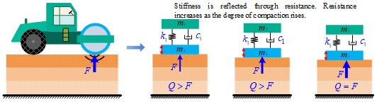
Figure 3: Reflecting changes in fill body stiffness through variations in resistance
The variation in the fill body’s resistance serves as the external manifestation of its changing stiffness. During compaction, the roller’s compaction force (Q) must exceed the fill body’s resistance (F) to break down the original soil structure, establish a new structural arrangement, and thereby increase stiffness (which, in turn, increases resistance). Upon the completion of the compaction process, the compaction force and the resistance become equal (Q = F). Consequently, when designing a road roller, the dynamic variation of this resistance must be considered.
4. Reconsidering the Interaction Model Between the Road Roller and the Fill Body
In traditional road roller design, the interaction between the roller’s vibrating drum and the fill body is typically characterized using a “mass-spring-damper” model (Figure 1). In this model, the resistance of the fill body is represented as a combination of the spring force and the damping force. The “mass” component in this context refers to the combined mass of the “participating soil volume” and the vibrating drum. However, the parameters within this traditional model are treated as fixed constants—implying a static, unchanging resistance—which does not accurately reflect actual field conditions. Therefore, this interaction model requires reconsideration and revision. Based on our research, utilizing variations in resistance to reflect changes in soil properties (specifically, stiffness) appears to be a viable technical approach (Figure 3). As for how this resistance model might be applied during the design process of a road roller, we intend to address this in a subsequent article (we may even develop a dedicated simulation system for this purpose).
A brief digression: If one still wishes to employ a two-degrees-of-freedom (2-DOF) model, the soil can be simplified into a massless spring (k2) coupled with a damper (c2), essentially setting the soil mass (m3) in Figure 1 to zero. Under this configuration, the lower assembly, comprising the vibrating drum (m2) and the soil elements (k2, c2), constitutes a single-degree-of-freedom (1-DOF) “main system” with a natural frequency of . Conversely, the upper assembly—consisting of the machine frame (m1) and its suspension elements (k1, c1), forms a 1-DOF “vibration isolation system” with a natural frequency of . When designing a road roller, the excitation frequency must be carefully selected to avoid coinciding with the natural frequency ω02; failure to do so risks damaging the mechanical components.
However, a tricky issue remains unresolved: the soil’s spring stiffness (k2) is inherently variable, causing the natural frequency ω02 to fluctuate as well (typically increasing over time). A potential solution is to allow the soil stiffness (k2) to vary over its full range (from low to high values) and calculate the corresponding natural frequencies (note: this does *not* represent the natural frequency of the soil itself). The road roller’s excitation frequency should then be designed to fall *outside* the range of these calculated natural frequencies—specifically, beyond the maximum calculated value—while also ensuring compatibility with the upper assembly’s vibration isolation system.
5. Explanations of Two Classic Illustrations
In the road roller industry, two classic examples originating in Europe are frequently cited. Both figures address the issue of resonance frequencies and are based on the two-degrees-of-freedom (2-DOF) model (it is worth noting that if a 2-DOF model were not adopted, the concept of natural frequencies—in this specific context—would not arise).
Figure 4 was presented by J.M. Machet at a conference held in Paris in 1976. This diagram was manually drafted based on data generated by computer simulation; the calculations were performed using a 2-DOF model and relied on specific assumptions regarding the model parameters (the assumed parameter values are provided in the figure itself). However, this diagram is incomplete, as it omits one of the two natural frequencies inherent to the system (a 2-DOF system must, by definition, possess two distinct natural frequencies).
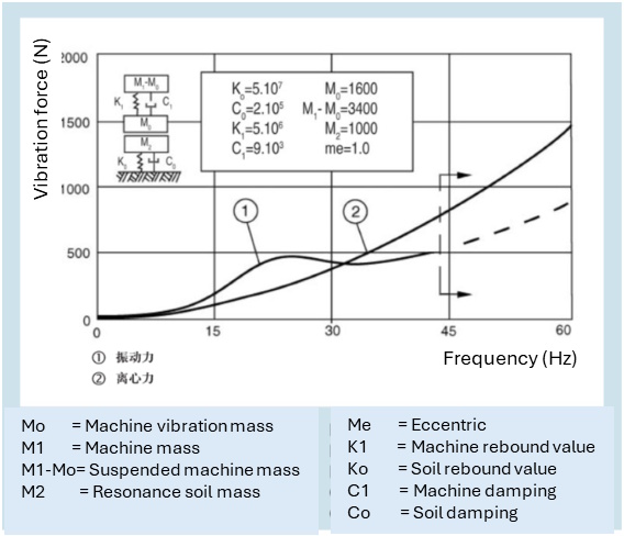
Figure 4: The Relationship Between Vibratory Force and Frequency
The “centrifugal force” referred to in Figure 4 is, in fact, the excitation force, while the “vibratory force” represents the compaction force (the pressure applied to the soil mass). Regarding the excitation force, the trend illustrated in the figure holds true, provided that the eccentricity (me) remains constant. As for the compaction force, the results presented in the figure are derived from a combination of spring forces and damping forces; although these results may not perfectly mirror actual field conditions, they nonetheless demonstrate a crucial design principle for vibratory rollers: the excitation frequency must be selected to avoid the system’s natural frequency (typically, the operating vibration frequency is designed to fall between 28 Hz and 30 Hz, deliberately avoiding the resonance frequency).
Based on the authors’ analyses utilizing a continuum mechanics model, the composition of the compaction force is considerably more complex than commonly assumed, and its relationship with the excitation frequency differs from that depicted in Figure 4. We will provide a detailed explanation of this subject at a later opportunity.
The question of how vibration frequency and amplitude affect compaction effectiveness has been a subject of discussion since the inception of vibratory rollers. The prevailing conclusion is that optimal compaction is achieved when the vibration frequency falls within the range of 25-50 Hz. However, within this specific frequency range, the variation in compaction effectiveness is not statistically significant, meaning that the vibration frequency itself does not substantially influence the ultimate compaction outcome (a conclusion that, in effect, refutes the so-called “resonance theory”). Conversely, a larger amplitude has been shown to yield superior compaction results and achieve greater compaction depth; this conclusion is clearly illustrated in Figure 5. This figure is reproduced from the publication *Vibratory Soil and Rock Fill Compaction* (1981), authored by the Swedish company Dynapac.
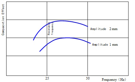
Figure 5: The Relationship Between Compaction Effectiveness, Frequency, and Amplitude
Furthermore, when dealing with coarser fill materials, it is necessary to increase both the amplitude and the compaction force to achieve optimal compaction results. However, when operating at increased amplitudes, the vibration frequency must be kept within reasonable limits; otherwise, there is a heightened risk of mechanical damage to the roller’s components.
In summary, the primary factors determining compaction effectiveness are compaction force and amplitude, whereas vibration frequency and rolling speed primarily influence the roller’s operational efficiency. The subsequent article in this series will delve deeper into this subject.
A Side Note: I invite you to consider the following question—why is impact compaction often more effective than vibratory compaction (setting aside, for the moment, the issue of surface unevenness)? Notably, the phenomenon of “resonance” does not occur in the context of impact compaction. Can, therefore, also be inferred that vibration frequency is not the primary factor influencing compaction effectiveness?
(End of Text)