Download PDF (English, Chinese)
Insights into Intelligent Compaction (Part 6): Supplementary Notes—Vibratory Compaction Mechanisms and Process Parameters (3)

(Continued from previous section)
3. Process Parameters in Vibratory Compaction
As previously mentioned, the composition of the vibratory compaction force is complex (see Figure 1). It involves specific process parameters and the coordination between them, representing a core technical aspect of vibratory roller design.
(1) Vibratory Compaction Process Parameters
Traditional vibratory compaction process parameters include vibrating mass (M), exciting force (P), excitation frequency (f) which can also be expressed as angular frequency (ω = 2πf), nominal amplitude (A0; actual amplitude A is greater than A0), and rolling speed (v). These parameters, provided by roller manufacturers and listed in specification tables, essentially describe the roller’s functional capabilities; they are also discussed in the *Intelligent Compaction* volume of this series. Different combinations of these parameters constitute distinct compaction processes.
A further breakdown reveals that the fundamental vibration parameters are simply M, m, e, and ω; P and A0 can be derived from them, as shown in Figure 4. Various combinations of M, m, e, and ω determine the exciting force (P) and nominal amplitude (A0) for specific compaction processes. Another parameter is a0, used to evaluate vibration intensity (actual intensity a is greater than a0).
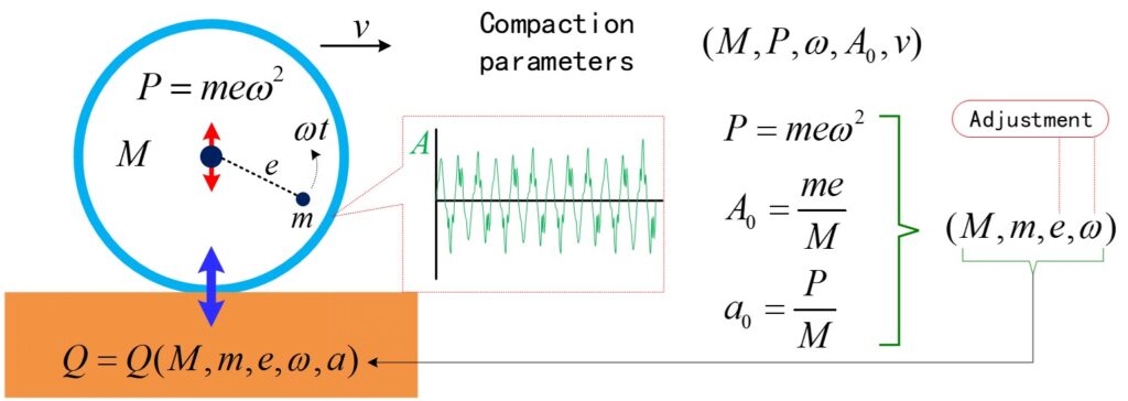
Figure 4: Vibratory compaction process parameters and their interrelationships
For a given vibratory roller, the vibrating mass (M) is constant, and the eccentric mass (m) is generally fixed. The adjustable parameters are primarily the eccentricity (e) and frequency (ω, controlled via rotational speed n). This adjustability forms one of the hardware foundations for the automatic regulation of compaction process parameters—specifically exciting force, nominal amplitude, and vibration frequency—a topic that will be explained in greater detail later in the discussion on intelligent rollers.
(2) Key Parameters
Among the vibratory compaction process parameters mentioned above, the exciting force (P) and nominal amplitude (A0) are particularly important. The magnitude of P determines the vibration intensity (a0) of the steel drum, while the magnitude of A0 determines the drum’s movement distance (vibration displacement) and depth of influence (the greater the amplitude, the stronger the impact energy of the vibrating drum on the surface being compacted, and the deeper the stress waves propagate). In the technical specifications for standard vibratory rollers, two levels of exciting force and two amplitudes are typically listed (while the vibration frequency is generally fixed); the combinations are usually “high exciting force + low amplitude” and “low exciting force + high amplitude.” A combination of “high exciting force + high amplitude” may cause damage to the machinery; please refer to the relevant content in the appendix of the *Intelligent Compaction* book series.
Vibration frequency serves two main purposes: first, adjusting the magnitude of the exciting force (though its impact on compaction force is limited); and second, regulating rolling efficiency (as the frequency indicates the number of load applications on the rolling surface per unit of time). Rolling speed also primarily affects rolling efficiency (if a higher speed is used, the number of passes must be increased to achieve the required compaction effect; see the appendix of the *Intelligent Compaction* series for details).
(3) Parameters required for engineering construction: compaction energy and compaction power
From an engineering construction perspective, users are primarily concerned with the roller’s performance—specifically, its ability to compact granular materials into a qualified structural body in the shortest possible time. Describing a roller’s capabilities using combinations of exciting force and nominal amplitude can seem somewhat abstract to users. Instead, we can evaluate performance using energy-based metrics, which offer a more intuitive perspective, as shown in Figure 5.
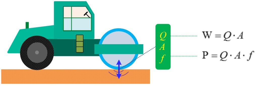
Figure 5: Compaction energy and compaction power
In Figure 5, W represents compaction energy (or compaction work), and P represents compaction power. Throughout the rolling process, both compaction energy and compaction power increase as the fill material’s capacity to absorb energy grows (with both Q and A increasing). When W and P cease to change, it indicates that the rolling operation under the current compaction process is complete. Conversely, these two parameters can also be used to evaluate the performance of vibratory rollers, thereby guiding the design of their vibration parameters.
A brief aside: the task of a road roller is to compact granular materials into a qualified fill structure, which constitutes its primary function. When designing a road roller, it is essential to account for factors related to the fill material and the variables involved in the compaction process, as well as to understand the interaction mechanism between the roller and the fill body. The “vibratory roller simulation system” we plan to develop—illustrated in Figure 6—may provide a solution to this challenge. By simply inputting the relevant parameters for the roller and the fill material, the system intelligently evaluates the suitability of the design’s vibration parameters and automatically generates optimized settings. This simulation system also facilitates an integrated design approach encompassing materials, structures, and construction processes.
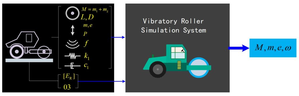
Figure 6: Simulation system for vibratory roller process parameters
(End of article)