Download PDF (English, Chinese)
Demystifying Intelligent Compaction Part II: Supplement—Performance Indicators and Interrelationships of Embankment Structures (2)

2. How to Obtain These Four Performance Indicators
Among these four indicators, stiffness is relatively the easiest to obtain. Whether it is the Resilient Modulus (E), the Secondary Deformation Modulus (Ev2), or the Subgrade Reaction Modulus (K30), all are derived through plate load tests. The only difference lies in the loading methods and data processing techniques employed. However, these tests remain relatively time-consuming and labor-intensive. Only Dynamic Modulus (Evd) is obtained using a Light Weight Deflectometer (LWD). While this method offers rapid testing speeds, the excitation energy generated is relatively low, so it is typically used solely for process control.
Additionally, it is important to note that plate load tests impose specific requirements regarding the particle size of the fill material: the maximum particle diameter must not exceed one-quarter of the bearing plate’s diameter—meaning it cannot exceed 7.5 cm.
In a field setting, both strength and stability are difficult to determine directly through testing. Consequently, these two performance characteristics are typically characterized indirectly by leveraging expressions correlated with stiffness. For instance, the magnitude of variation in the modulus E(t) serves as an indicator of stability. Naturally, these parameters can also be determined through accelerated loading tests. However, such tests are both time-consuming and labor-intensive, require extremely expensive equipment, and the simulated test conditions often differ significantly from actual, real-world conditions.
To ensure uniformity, it is necessary to determine stiffness at every point along the roadway alignment’s longitudinal axis to accurately assess the spatial distribution of mechanical properties. This necessitates adopting a continuous stiffness measurement methodology. Clearly, measurement techniques based on plate load tests are incapable of achieving this; even a Falling Weight Deflectometer (FWD) does not allow for truly continuous measurement. However, by using the rollers employed during construction, it is possible to continuously measure the stiffness of the fill embankment—this capability constitutes the “sensing technology” at the core of intelligent compaction systems.
3. The Interrelationships Among the Four Indicators
The four performance indicators for fill embankments discussed above can also be derived from the perspective of the embankment’s *function* (or *requirements*—which also constitute the ultimate design objectives). (In this context, “function” refers to the specific role performed by the fill embankment—essentially the external manifestation of its inherent performance characteristics; for a detailed exposition, please refer to the discussion on “systems” in Chapter 2 of the *Introduction* volume within this book series.) Building upon this foundation, a subsequent analysis reveals intrinsic interconnections among these four indicators; the unifying link—the central nexus binding them—is *stiffness*, as illustrated in Figure 2.
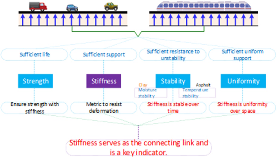
Figure 2: The Bridging Role of Stiffness
Among the four key performance indicators—strength, stiffness, stability, and uniformity—stiffness is the critical parameter for ensuring a fill body can effectively support traffic loads. It is the most significant physical parameter in elasticity theory and an indispensable element in mechanical calculations and analyses. The other three indicators can be characterized, either directly or indirectly, in terms of stiffness; this characterization is derived from their inherent physical significance. Figure 3 presents a diagram illustrating the interconnections among these indicators, thereby facilitating a clearer understanding of their relationships.
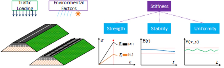
Figure 3: Diagram Illustrating the Interconnections Among Fill Body Performance Indicators
Regarding strength: although it cannot be characterized *directly* using stiffness, practical experience has demonstrated that structural bodies possessing high stiffness also tend to exhibit high strength. Thus, a broadly positive correlation exists between the two. For fill-type structures, greater stiffness generally translates into a longer service life (conversely, in areas exhibiting early-stage deterioration, the local stiffness degrades significantly, resulting in a loss of load-bearing capacity).
Regarding stability: fundamentally, stability represents the fill body’s capacity to maintain its stiffness without undergoing significant alteration when subjected to traffic loads and natural environmental influences. This capacity can be characterized by the variation curve of the elastic modulus over time, E(t) (for specific details on its mathematical formulation, refer to the discussion on Lyapunov stability found in the “Engineering Control Technology” volume of the relevant book series). When dealing with materials sensitive to moisture and temperature fluctuations, it is essential to enhance both moisture and thermal stability to ensure overall stiffness stability.
Regarding uniformity: this refers to the consistency of stiffness distribution across a horizontal plane—specifically, ensuring that the magnitude of variation in the elastic modulus, E(x, y), remains confined within a prescribed range. In principle, this permissible range of stiffness variation should be determined based on the extent of non-uniform support that the traffic loads can tolerate. In current Chinese standards for intelligent compaction, this aspect is typically addressed through a simplified approach.
4. The Central Status of the Stiffness Indicator
The aforementioned analysis clearly highlights the central status that stiffness occupies among the performance indicators for fill bodies. By assessing the magnitude of stiffness, one can indirectly evaluate the expected service life; by analyzing how stiffness varies over time, one can gauge the degree of structural stability; and by examining the spatial distribution of stiffness across a plane, one can identify and characterize conditions of non-uniformity.
Consequently, by acquiring comprehensive data on stiffness at every point within a fill body—along with information regarding how that stiffness evolves over time—one can attain a holistic understanding of the fill body’s mechanical performance. This fact underscores, once again, the critical importance of the stiffness indicator. Consequently, comprehensively determining stiffness at every point within the embankment body has emerged as a critical issue.
5. How to Construct an Embankment Body That Meets Requirements
As illustrated in Figure 2, the embankment body must satisfy (design) requirements across four key aspects—strength, stiffness, stability, and uniformity—thereby providing a guarantee for safe vehicle operation. How, then, can the embankment body be constructed to achieve this objective? There is but one answer: by selecting appropriate fill materials (a responsibility of the design phase) and, in strict accordance with technical specifications, constructing (compacting) these loose materials into a qualified embankment structure (a responsibility of the construction phase). This process can be summarized as follows: meticulous design, scientific compaction, and rigorous quality control.